1. The resistance of a conductor varies directly as its length.
2. The resistance of a conductor varies inversely to its cross section area.
3. The resistance of a conductor depends on the material.
4. The resistance of a conductor depends on its temperature.
The above factors can be summed up mathematically as :
![]()
where ρ is constant representing the nature of material and is known as specific resistance.
Effect of Temperature on Resistance
(a) Resistance of pure metals and alloys increases with rise in temperature.
(b) Resistance of electrolytes, insulators and semiconductors decreases with rise in temperature.
If Ro = Conductor resistance at 0˚C
Rt = Conductor resistance at t˚C
t = rise in temperature
and αo = Temperature coefficient of resistance at 0˚C,
Then Rt = Ro (1 + αot)
The temperature coefficient at 0˚C is defined at the change in resistance per ohm for a rise in temperature of 1˚C from 0˚C.
A single cell has an e.m.f. of about 1.5 volts. If either more voltage is needed or more current is required, then cells are connected either in series or in parallel respectively. This arrangement of connection is named as grouping of cells.
When cell are connected in series, e.m.f. of the battery is equal to the sum of the e.m.f. of cells.
Internal resistance of battery =sum of internal resistance of cells.
e.m.f. of battery E =ne
where e is e.m.f. of the cell and n refers to the number of cells in series.
The cells when arranged in parallel have the same e.m.f., but internal resistance of the unit is reduced.
If n cells are connected in parallel, each of e.m.f. E,
then
e.m.f. of the battery = e.m.f. of one cell = E
![]()
where r is the resistance of one cell
Cells in Series and in Parallel
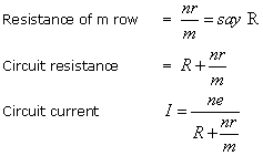
n = number of cells in each row
m = number of parallel rows.
N = total number of cells = mn.
Let e.m.f of one cell =e
E.M.F. of battery =ne volts
Internal resistance of each row =nr ohms
The efficiency of a Cell is considered in two ways:
(1) Ampere-hour (A.h) efficiency.
(2) Watt-hour (W.h.) efficiency.

D.C. motors are classified according to the method of excitation. They may be of the shunt, series or compound types.
Series Motor
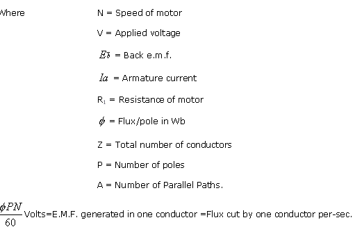
The speed of a series motor is given by the relation:

Shunt motor

where Ra is the armature resistance. Since ![]() is practically constant at all loads, speed is there almost constant.
is practically constant at all loads, speed is there almost constant.
The two main types of winding are:
-
Lap Winding. It is also known as parallel winding or multiple winding. In this type of winding, the numbers of parallel paths (A) are equal to the number of poles (P).
-
Wave Winding. In this case the armature conductors are divided into two parallel irrespective of the number of poles.
The rotor of induction motor rotates at somewhat lesser speed than the synchronous speed and actual speed is known as slip.
![]()
where Nr is rotor or actual while N is synchronous speed.
![]()
AC through Resistance and Inductance
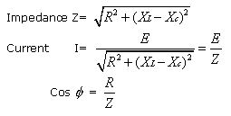
In the resistance part of the circuit the current is in phase with the voltage, while in the inductive part it is 90˚ out of phase. Hence, to determine the current, the effect of resistance and reactance has to be combined which is named as impedance:

where ![]() is the phase angle between the voltage and current and cos
is the phase angle between the voltage and current and cos ![]() is called the power factor.
is called the power factor.
Circuits Containing Resistance, Inductance and Capacitance
Transformer is a device for transferring energy from one alternating current circuit to another without any change in frequency. It changes voltage from high to low and low to high with a corresponding increase or decrease in current. If the voltage is increased, the transfer is said to be stepped up. If it is decreased, then it is referred as step down.

Whenever the supply is three phase and it is desired to transform current at another voltage, then either a single three phase transformer or three separate single phase transformers can be used. However, in practice a single three phase transformer is used. The three phase winding of a transformer can be connected either in star or in delta.
Current and voltage in star
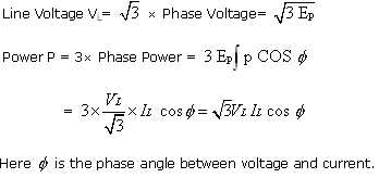
The e.m.f. between any line and the neutral gives the phase voltage while the e.m.f. between two outer terminals is known as line voltage.
Current in each line is the same as phase current
i.e. Line current IL=Phase current IP
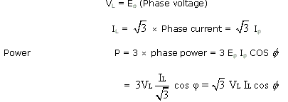
Line Voltage and Current in Delta


0 comments:
Post a Comment