Introduction
Kirchoff discovered this: the total current entering a node equals the total current leaving a node! And, these currents can be described by an equation of voltages and conductances. If you have more than one node, then you get more than one equation describing the same system (simultaneous equations). The trick now is finding the voltage at each node that satisfies all of the equations simultaneously.
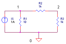
Circuit Example Here’s a simple circuit example.
Another way of stating the KC Law is this: the sum of currents in and out of a node is zero. This makes writing nodal equations a piece of cake. The two equations for the two circuit nodes look like this.

Because our mission is to calculate the node voltages, let’s reorganize the equations in terms of V1 and V2.

So here sit V1 and V2 in the middle of two different equations. The trick is finding the values of V1 and V2 that satisfy both equations. But how?
SOLUTION #1 – WORK THE EQUATIONS
Just roll up your sleeves and solve for V1 and V2. Before we begin we’ll make bookkeeping easy by writing the resistors in terms of total conductance: G11 = 1/R1 + 1/R2, G12 = -1/R2, G21 = -1/R2 and G22 = 1/R2+1/R3. The system equations now look like this.
![]()
First, solve the second equation for V1
![]()
Then, stick this into the first equation and solve for V2

Okay, it’s a little messy, but we’ve got V2 described by circuit conductances and Is only! After V2 is calculated numerically, stick it back into V1 = – G22 ∙V2 / G21 and there you have it, circuit voltages V1 and V2 that satisfy both system equations.
SOLUTION #2 – THE MATRIX
Solution #1 looks reasonable for simple circuits, but what about medium or large circuits? The bookkeeping of terms spins out of control quickly. What’s needed is a more methodical and efficient solution: Enter the Matrix. Here’s the set of nodal equations written in matrix form.

Or, in terms of total conductances and source currents

Treating each matrix as a variable, you can write
G ∙ v = i
In the matrix world, you can solve for a variable (almost) like any other algebraic equation. Solving for v you get
v = G-1∙ i
Where G-1 is the matrix inverse of G. ( 1 / G does not exist in the matrix world.) This equation is the central mechanism of the SPICE algorithm. Regardless of the analysis – AC, DC, or Transient – all components or their effects are cast into the conductance matrix G and the node voltages are calculated by v = G-1∙ i , or some equivalent method.
LINEAR DC ANALYSIS
Armed with Nodal Analysis and an Excel spreadsheet, you can perform Linear DC Analysis on the circuit above. Download and open the spreadsheet . Enter the circuit values under the variables shaded light blue.
| R1 | R2 | R3 | Is |
| 10 | 1000 | 1000 | 1 |
How much voltage would you estimate at nodes 1 and 2? You can expect V1 = Is ∙ R1 =
1 A ∙ 10 ohms = 10V. That’s because R2 and R3 have little effect on 10 ohms. At node 2, the simple R2-R3 divider should produce about V2 = 5V.
First, the spread sheet calculates the conductance matrix G
| 0.101 | -0.001 |
| -0.001 | 0.002 |
according to the equations
| 1/R1 + 1/R2 | -1/R2 |
| -1/R2 | 1/R2 + 1/R3 |
Next, Excel inverts G and multiplies the result G-1 by i to get v. ( See how Excels inverts and multiplies matrices below.)
G-1 x i = v
| 9.95 | 4.98 | x | 1 | = | 9.9502 |
| 4.98 | 502.49 |
| 0 |
| 4.9751 |
And there you have it, just like the SPICE engine, we’ve computed the circuit’s voltages! Pick other values for R1 like 1 or 100 Ω. Does the output scale up and down as expected? Change R2 or R3. Vary Is or change its polarity.
HANDS-ON DESIGN Try adding another resistor to the circuit. For example, place R4 in parallel with R3. Write out the nodal equations. Then include R3 in the cell formulas that form G. The Excel formulas should effectively calculate the following.
| 1/R1 + 1/R2 | -1/R2 |
| -1/R2 | 1/R2 + 1/R3 + 1/R4 |


0 comments:
Post a Comment