Showing posts with label circuit elements. Show all posts

November 25, 2011

Mobile phone call indicator

Purpose
This circuit can be used to escape from the nuisance of mobile phone rings when you are at home. This circuit will give a visual indication if placed near a mobile phone even if the ringer is deactivated. This circuit was designed to detect when a call is incoming in a cellular phone (even when the calling tone of the device is switched-off) by means of a flashing LED.

The device must be placed a few centimeters from the cellular phone, so its sensor coil L1 can detect the field emitted by the phone receiver during an incoming call.

Device operation

When a call is coming to the mobile phone, the transmitter inside it becomes activated. The  frequency of the transmitter is around 900MHz.The  coil L1 picks up these oscillations by induction and feds it to the base of Q1. This makes the transistor Q1 activated.Since the Collector of Q1 is connected to the pin 2 of IC1 (NE555) , the IC1 is triggered to make the LED connected at  its output pin (pin 3) to blink. The blinking of the LED is the indication of incoming call.

The signal detected by the sensor coil is amplified by transistor Q1 and drives the monostable input pin of IC1. The IC's output voltage is doubled by C2 & D2 in order to drive the high-efficiency ultra-bright LED at a suitable peak-voltage.

Note:

  • Stand-by current drawing is less than 200µA, therefore a power on/off switch is unnecessary.
  • Sensitivity of this circuit depends on the sensor coil type.
  • L1 can be made by winding 130 to 150 turns of 0.2 mm. enameled wire on a 5 cm. diameter former (e.g. a can). Remove the coil from the former and wind it with insulating tape, thus obtaining a stand-alone coil.
  • A commercial 10mH miniature inductor, usually sold in the form of a tiny rectangular plastic box, can be used satisfactorily but with lower sensitivity.
  • IC1 must be a CMos type: only these devices can safely operate at 1.5V supply or less.
  • Any Schottky-barrier type diode can be used in place of the 1N5819: the BAT46 type is a very good choice.

June 17, 2011

Operational Amplifier

OPAMP
 
The operational amplifier is arguably the most useful single device in analog electronic circuitry. With only a handful of external components, it can be made to perform a wide variety of analog signal processing tasks. It is also quite affordable, most general-purpose amplifiers selling for under a dollar apiece. Modern designs have been engineered with durability in mind as well: several "op-amps" are manufactured that can sustain direct short-circuits on their outputs without damage.

The Operational Amplifier is probably the most versatile Integrated Circuit available. It is very cheap especially keeping in mind the fact that it contains several hundred components. The most common Op-Amp is the 741 and it is used in many circuits.
The OP AMP is a ‘Linear Amplifier’ with an amazing variety of uses. Its main purpose is to amplify (increase) a weak signal - a little like a Darlington Pair.

The OP-AMP has two inputs, INVERTING ( - ) and NON-INVERTING (+), and one output.

Working in 2 ways

1. An inverting amplifier. Leg two is the input and the output is always reversed.

In an inverting amplifier the voltage enters the 741 chip through leg two and comes out of the 741 chip at leg six.If the polarity is positive going into the chip, it negative by the time it comes out through leg six.The polarity has been ‘inverted’.

GAIN (AV) = -R2 / R1

2. A non-inverting amplifier. Leg three is the input and the output is not reversed.

In a non-inverting amplifier the voltage enters the 741 chip through leg three and leaves the 741 chip through leg six. This time if it is positive going into the 741 then it is still positive coming out. Polarity remains the same.

GAIN (AV) = 1+(R2 / R1)


OPAMP AS COMPARATOR

However, this time the 741 is used as a comparator and not an amplifier. The difference between the two is small but significant. Even if used as a comparator the 741 still detects weak signals so that they can be recognised more easily. It is important to understand these circuits as they very regularly appear in examinations.

A ‘comparator’ is an circuit that compares two input voltages. One voltage is called the reference voltage (Vref) and the other is called the input voltage (Vin).When Vin rises above or falls below Vref the output changes polarity (+ becomes -).


Positive is sometimes called HIGH. Negative is sometimes called LOW

July 26, 2009

Transformer

In real this is how an TRANSFORMER looks like..
the transformer is a device that transfers electrical energy from one end of the coil to the another coil by mutual induction method......

http://upload.wikimedia.org/wikipedia/commons/7/7a/Transformer-hightolow_smaller.jpg

Introduction of transformer..

A transformer makes use of Faraday's law and the Ferromagnetic properties of an iron core to efficiently raise or lower AC voltages. It of course cannot increase power so that if the voltage is raised, the current is proportionally lowered and vice versa.

How the ideal transformer looks like
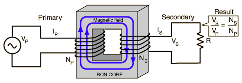


Relation between transformers & Faraday's law..
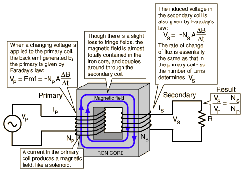


Formulas for transformers.............


Concepts of transformers...............
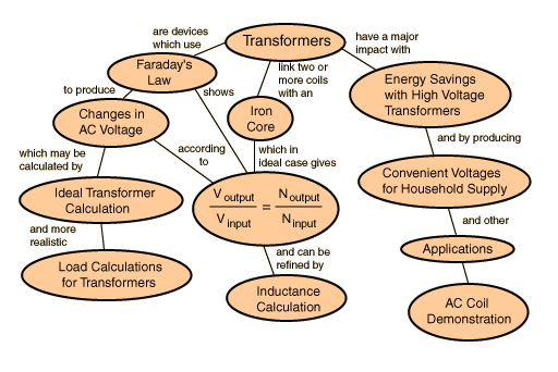


Types of transformers...

STEPUP TRANSFORMER:-

http://www.physics.sjsu.edu/becker/physics51/images/32_16_Step-up_transformer.JPG

A "step-up transformer" allows a device that requires a high voltage power supply to operate from a lower voltage source. The transformer takes in the low voltage at a high current and puts out the high voltage at a low current.

STEPDOWN TRANSFORMER:-

http://wpcontent.answers.com/wikipedia/commons/thumb/6/64/Transformer3d_col3.svg/350px-Transformer3d_col3.svg.png

A "step-down transformer" allows a device that requires a low voltage power supply to operate from a higher voltage. The transformer takes in the high voltage at a low current and puts out a low voltage at a high current.

Common Types of Transformer...

Following are the few common types of transformer

Power Transformer - These operate at 50 to 400 Hz at a absolute nominal line voltage from 105 to 130 V. They are actually made with single and multiple secondaries with various step-up and step-down turns ratios.

Secondary Transformer - Secondaries transformer could have a single tap, multiple taps and even sometimes no tap. Some units are prepared with a tapped primary. Output voltage could start ranging from three to several thousand volts with output currents from .01 to 1500 A.

The Cores Transformer - The cores transformers are made up of iron or steel laminations. They are packaged in a hermetically sealed case especially for military or space use or with an open frame or even plastic enclosure for commercial, consumer or any industrial use.

Isolation Transformer - These types of transformer operate with a one-to-one turn’s ratio between primary and secondary, as isolating the line from the secondary load. Usually, an isolation transformer further comprises of Faraday shield, which is in fact a screen of nonmagnetic metal wound between the primary and secondary and then connected to the transformer core.

The Shield Transformer - The shield transformer acts particularly to prevent capacitive coupling of spurious signals and sound between windings, and it as well reduces transformer efficiency by improving leakage current.

Control Transformer - These are used as small power transformer for controlling components like relays and low voltage ac control devices. Common output voltages come in 12 and 24 Vac at current capabilities of 4 to16 A.

Autotransformer - Autotransformers are types of single winding with either fixed or variable step-up or step-down turn’s rations. They are actually smaller and less pricey than the two-winding types.

Audio Transformer - These vary from the power transformer types in, which they are used to give matching electrical characteristics of an output amplifier to that of any normal load speaker. In high-fidelity audio systems, they further operate from 20 Hz to 20 KHz. This audio transformer comprises of voice communications only and operates from 200 to 500 Hz.

Radio Frequency Transformer - These radio frequency transformers operate at a fixed high frequency with a capacitor across primary, secondary or sometimes even both to create a tuned or resounding circuit. Most types normally use an air core; however some are made up of ferrite slug to allow any sort of adjustment for inductance windings over a given range. They are generally assembled in aluminum-shielded container to reduce pickup or radiation of magnetic fields.

Pulse Transformer - These types are used for the generation and transmission of square wave pulses with emphasis on fast rise and fall times of the pulse and high-frequency response. These transformers are packaged in a miniature enclosure, 1/4 inch to 1/2 inch in diameter, and use an air core.


Working of transformer................


Transformer refers to the static electromagnetic setting which can transfer power from one circuit to another one. In AC circuits, AC voltage, current and waveform can be transformed with the help of Transformers. Each transformation is usually to transfer from one circuit to another one by the way of electromagnetism, but it has no direct relation with this circuit. It also can be transformed through electromagnetism (electrical manner). This electromagnetism is known as auto-transformer.
   Transformer plays an important role in electronic equipment. AC and DC voltage in Power supply equipment are almost achieved by transformer’s transformation and commutation. At the same time the electrical parameters transformed by transformer are not one but a few ones.
Most of the isolation, matching and impedance in the circuit carry out by transformer.  Most of isolation, matching and impedance in the circuit carry out by transformer.Simple schematic diagram of the transformer is shown in (1-1). It is connected by closed-magnet (iron cores), two windings and AC power supply. The winding is called the primary winding; another winding is connected with load, and it is called secondary windings.

No-load state of Transformer: viz. the disconnecting state between he secondary winding and load (Figure 1-2). Connect the primary winding and the power supply of AC voltageU1, and then it will produce alternating current I0, this current is called no-load currents. This current set up alternating magnetic flowφ0 which is closed along iron core magnetic circuit. At the same time, it traverses the primary winding and secondary winding, and then produces inducting electromotive forceE2 (secondary no-load voltage).


Circuit symbol for transformers...

circuit symbol Transformer with two windings and iron core.
circuit symbol Step-down or step-up transformer. The symbol shows which winding has more turns, but not usually the exact ratio.
circuit symbol Transformer with three windings. The dots show the relative configuration of the windings.
circuit symbol Transformer with electrostatic screen preventing between the windings.

July 10, 2009

Cell and Battery

A Cell
A cell is a very small battery. A good example is the type found in most modern watches. This type of battery is often used in camcorders as backup batteries. They ensure that the date and time are held in memory even when the rechargeable batteries are removed. Button batteries are usually rated at 1.5 volts or 3 volts and consequently they are used in devices that need very little power. Watches are ideal for this type of battery as well as low power calculators and hearing aids. Large button batteries are used as backup batteries for the CMOS of computer systems and ensure that the basic settings in the setup of the computer are held in memory, even when the computer is switched off.


This is how it looks


Battery

Batteries come in all shapes and sizes. They store electrical charge and as we all know when they are put into an electronic device such as a portable radio, they provide the power.most commonly used batteries are1.5 volts and 9 volts.
School projects are powered by batteries because they are safe, easily buy and safe.


Simple Circuit

This shows one of the most simple circuits. When the switch is pressed, the LED (further information below) lights. Resistors are used in circuits because LEDs can be destroyed by voltages over 3 volts. Why do you think the circuit opposite does not have a resistor to protect the LED ?

Each battery is 1.5 volts. The two batteries are connected in ‘series’, they are both linked positive to negative and this gives us a total of 3 volts. Therefore, the LED is safe from damage.


Same Circuit Using a CELL


Now in this circuit only when the circuit is closed the LED will Glow.

June 27, 2009

LIGHT DEPENDENT RESISTORS

In real this is how an LDR looks like..

A Light Dependent Resistor (aka LDR, photoconductor, or photocell) is a device which has a resistance which varies according to the amount of light falling on its surface.


Symbol for LDR

Light sensor circuit

Opposite is a simple light/ dark sensor. This can be connected as an input or switch to another circuit. The sensors has three green wires (1, 2 and 3). Wire 2 should always be connected to one of the inputs. If wire 1 is also connected then the sensor acts as a dark sensor. If wires 2 and 3 are connected to the inputs then sensor operates as a light sensor.

light sensor circuit click for next stage

Functions of LDR...


An LDR and a normal resistor wired in series across a voltage, say 5V DC, can be used to develop a signal. Depending on which is tied to the 5V and which to 0V, the voltage at the point between them, call it the sensor node, will either rise or fall with increasing light. If the LDR is the component tied directly to the 5V, the sensor node will increase in voltage with increasing light. It doesn't really matter which way (rise or fall) because the designer has a choice of several simple circuits to invert the signal as needed for whatever function is to be performed.

This voltage at the sensor node (between the components) will vary gradually with the light level. To use for security light control, it's desired to develop a signal that switches level from one extreme to the other suddenly as light level goes from light to darker and darker. This result could be called a binary signal, a signal with two states (perhaps about 4V and 0.5V), indicating yes/no or 1/0. To develop this, the sensor node voltage can be compared, by an electronic circuit, with some threshold voltage to determine whether the light level is more or less than the threshold. The result of the comparison would give a "DARK? yes/no" determination.


Working of LDR:-

http://home.zonnet.nl/rsetteur/aquarium/karel/colorie/images/led_ldr.jpg

Typically, photocells only operate at low current, so you don't want to use them to directly drive a load, they're more for sensors. However, if you connect a positive voltage source in series with the photocell and then connect the other end to the gate of a transistor, you can use the transistor to drive the load, such as an LED. That way, if you shine a light on the photocell, the LED will turn on. In the sources is a good graphical representation and explanation of this.


Applications

Photoconductive cells are used in many different types of circuits and
applications.

Analog Applications

· Camera Exposure Control
· Auto Slide Focus - dual cell
· Photocopy Machines - density of toner
· Colorimetric Test Equipment
· Densitometer
· Electronic Scales - dual cell
· Automatic Gain Control – modulated light
source
· Automated Rear View Mirror

Digital Applications

· Automatic Headlight Dimmer
· Night Light Control
· Oil Burner Flame Out
· Street Light Control
· Absence / Presence (beam breaker)
· Position Sensor

Formula
:

This formula is responsible for calculating the output power of LDR

June 26, 2009

Integeated Circuits(IC)

In real this is how an IC looks like..


First IC that was ever created ..


Introduction of
IC
Integrated Circuits are usually called ICs or chips. They are complex circuits which have been etched onto tiny chips of semiconductor (silicon). The chip is packaged in a plastic holder with pins spaced on a 0.1" (2.54mm) grid which will fit the holes on stripboard and breadboards. Very fine wires inside the package link the chip to the pins.


IC pin numbersPin numbers
The pins are numbered anti-clockwise around the IC (chip) starting near the notch or dot. The diagram shows the numbering for 8-pin and 14-pin ICs, but the principle is the same for all sizes.


Common ICs

Below, the most common ICs are shown. (Those parts that I use most.)
For extensive details on each part, see the corresponding data sheet.
The part numbers of the SN74 series ICs are written with a 74, often followed by LS or HC.
LS (Low power Shottky) indicates low power consumption. HC indicates the device is High speed C-MOS (Complementary-Metal Oxide Semiconductor), and is also a low power consumption IC.
The average current consumption for each type of chip is listed below.
The current shown is for when the device is in a LOW state output. In the case of the LOW state output, current consumption is much greater than in the HIGH state output.
SN7400-----22mA
SN74LS00-----4.4mA
SN74HC00-----0.02mA

Several kinds of ICs are not available in the LS or HC type. For example, SN7445 is not available in LS or HC. It is available only as SN7445, the normal type.

NameFunctionVccPin Assign(Top View)Remarks
SN74HC00Quad 2 Input NAND+5V2 input NAND circuits entered 4 pieces
SN74HC04Hex Inverters+5V Inverter circuit entered 6 pieces
Details
SN74LS42 BCD to DECIMAL
Decoder
+5VOne of output takes LOW state serected by the binary input.
SN7445 O.C. BDC to DECIMAL
Decoder/Driver
+5V Open collector type of 7442

Max current of output is 80mA.
SN74LS47 BCD to Segment
Decoder/Driver
+5V Front View
Driving IC of ‚Vsegments LED.
Open collector type
Max resistance voltage:15V
6 and 9 disply type:
Related 74247
SN74HC73 Dual JK-FFs
With Clear
+5V2 pieces of JK-FF
SN74LS90Decade Counter+5V Asynchronous 2 + 5 counter.
Async preset : 9
Async clear
Related
74290
74390
SN74HC93 4-Bit Binary
Counter
+5VAsynchronous 2 + 8 counter.
SN74HC123 Dual Retriggaerable
Single Shot
+5V Single shot resister holds the output in the required time from the input states goes to ON.
The output holding time corresponds to C(capacitor) and R(resistor) connected to the Cext(External capacitor) and Rext(External resistor) respectivly.
SN74LS247 BCD to Segment
Decoder/Driver
+5V Front View

6 and 9 disply type:
Related 7447
SN74LS290Decade Counter+5V This type is the same as the SN7490, with a different layout of pins.
Related
7490
74390
SN74HC390 Dual Decade
Counters
+5V Type that inserted 2 SN7490.
Presetting 9 is omitted .
Related
7490
74290
4040B 12Bit Binary
Counter
(CMOS)
+5V 12-stage Binary counter.
It has a clear function.
Counts downward with an external clock pulse.
4541B Progarammable
Oscillator/Timer
(CMOS)
+5V Programmable 16 stage binary counter.
Used in RC oscillation circuits, power reset, output control circuits.
Tap outputs of 8, 10, 13, 16 bits are possible by the control terminal.
NE555Timer+4.5 to +16V Max frequency: 500kHz
Temperature drift: 0.005%/°C.
Max output current: 200mA.
Delay time setting
:several micro sec to several hours
LM386N-1Low frequency electric power amplifier+4 to 12V Max output: 660mW
Load: 8 to 32-ohm
Waiting current: 4mA
LM386N-4Low frequency electric power amplifier+5 to 18V


Max output: 1.25W
Load: 8 to 32-ohm
Waiting current: 4mA
TA7368PLow frequency electric power amplifier+2 to +10V Max output: 1.1W
Load: 4 to 16-ohm
uPC319Voltage comparator 5 to 18V

±5
to
±18V
Standard general use comparator with single power supply/dual power supply operation

Other compatible ICs
LM319
NJM319
AN1319
7975 Multi-melody IC
(CMOS)
+1.5 to +3V Melody IC that includes 8 pre-programmed melodies.
It has 2 sound resources and a settable envelope.

Title
Green-Sleeves
Fur Elise
Heavenly Creatures
Ich bin ein musikante
Valse Favorite
Holderia
Amaryllis
Home On The Range


Three Terminal Voltage Regulator


It is very easy to get stabilized voltage for ICs by using a three terminal voltage regulator.
The power supply voltage for a car is +12V - +14V. At this voltage, some ICs can not operate directly except for the car component ICs. In this case, a three terminal voltage regulator is necessary to get the required voltage.
The three terminal voltage regulator outputs stabilized voltage at a lower level than the higher input voltage. A voltage regulator cannot put out higher voltage than the input voltage. They are similar in appearance to a transistor.

On the left in the photograph is a 78L05. The size and form is similar to a 2SC1815 transistor.
The output voltage is +5V, and the maximum output current is about 100mA.
The maximum input voltage is +35V. (Differs by manufacturer.)

On the right is a 7805. The output voltage is +5V, and maximum output current is 500mA to 1A. (It depends on the heat sink used)
The maximum input voltage is also +35V.

There are many types with different output voltages.
5V, 6V, 7V, 8V, 9V, 10V, 12V, 15V, 18V


Component Lead of Three Terminal Voltage Regulator


Because the component leads differ between kinds of regulators,

you need to confirm the leads with a datasheet, etc.


    Example of 78L05
    Part number is printed on the flat face of the regulator, and indicates the front.

    Right side : Input
    Center : Ground
    Left side : Output


Example of 7805
Part number is printed on the flat face of the regulator, and indicates the front.

Right side : Output
Center : Ground
Left side : Input

Opposite from 78L05.


DOOR BELL FOR DEAF CLICK HERE

Electronics is the study and use of electrical that operate by controlling the flow of electrons or other electrically charged particles in devices such as thermionic valves. and semiconductors. The pure study of such devices is considered as a branch of physics, while the design and construction electronic circuits to solve practical problems is called electronic engineering.

Popular article