INTRODUCTION
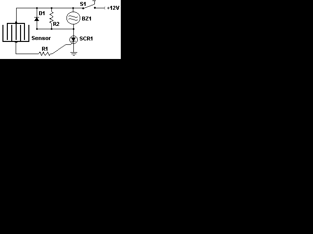
This circuit uses a sensor made of a small piece of etched PC board and a simple SCR circuit to detect rain and sound a buzzer. The SCR could also be used to activate a relay, turn on a lamp, or send a signal to a security system.
circuit diagram:-
parts required
| R1 | 1 | 1K 1/4 W Resistor | |
| R2 | 1 | 680 Ohm 1/4 W Resistor | |
| D1 | 1 | 1N4001 Silicon Diode | |
| BZ1 | 1 | 12V Buzzer | |
| S1 | 1 | SPST Switch | |
| SCR1 | 1 | C106B1 SCR | 106CY |
| SENSOR | 1 | See Notes | |
| MISC | 1 | Board, Wire, Case, PC Board (For Sensor) |
Notes
- The sensor is a small piece of PC board etched to the pattern showen in the schematic. The traces should be very close to each other, but never touching. A large spiral pattern would also work.
- Make sure to use a loud buzzer.


0 comments:
Post a Comment