Showing posts with label PROJECTS. Show all posts

July 03, 2013

50 Watts Inverter Circuit

A 50 watt inverter might look quite trivial, but it can serve some useful purposes to you. When outdoors, this small power house can be used for operating small electronic gadgets, soldering iron, table top radios, incandescent lights, fans etc.
Let’s learn how to build this homemade 50 watt inverter unit, beginning with a brief description regarding the circuit diagram and its functioning:

Circuit Description

The circuit may be understood with the following points:
Referring to the figure, transistors T1 and T2 along with the other R1, R2, R3 R4, C1 and C2 together form a simple astable multivibrator (AMV) circuit. A multivibrator circuit basically is composed of two symmetrical half stages, here its formed by the left and the right hand side transistor stages which conduct in tandem or in simple words the left and the right stages conduct alternately in a kind of a perpetual “motion”, generating a continuous flip flop action.
The above action is responsible of creating the required oscillations for our inverter circuit. The frequency of the oscillation is directly proportional to the values of the capacitors or/and the resistors at the base of each transistor.
Lowering the values of the capacitors increases the frequency while increasing the values of the resistors decreases the frequency and vice versa. Here the values are chosen so as to produce a stable frequency of 50 Hz.
Readers, who wish to alter the frequency to 60 Hz, may easily do it by just changing the capacitor values appropriately.
Transistors T2 and T3 are placed at the two output arms of the AMV circuit. These are high gain; high current Darlington paired transistors, used as the output devices for the present configuration.
The frequency from the AMV is fed to the base of T2 and T3 alternately which in turn switch the transformer secondary winding, dumping the entire battery power in the transformer winding.
This results in a fast magnetic induction switching across the transformer windings, resulting the required the mains voltage at the output of the transformer.

Parts Required

You will require the following components for making this 50 watt homemade inverter circuit:
R1, R2 = 100K,
R3, R4 = 330 Ohms,
R5, R6 = 470 Ohms, 2 Watt,
R7, R8 = 22 Ohms, 5 Watt
C1, C2 = 0.22 uF, Ceramic Disc,
D1, D2 = 1N5402 or 1N5408
T1, T2 = 8050,
T3, T4 = BC316,
T5, T6 = 2N3055 (TO-220)
General purpose PCB = cut into the desired size, approximately 5 by 4 inches should suffice.
Battery: 12 volts, Current not less than 10 AH.
Transformer = 9 – 0 – 9 volts, 5 Amps, Output winding may be 220 V or 120 volts as per your country specifications
Sundries: Metallic box, fuse holder, connecting cords, sockets etc
 
Testing and Setting Up the Circuit

After you finish making the above explained inverter circuit, you may do the testing of the unit in the following manner:
Initially do not connect the transformer or battery to the circuit.
Using a small DC power supply power the circuit.
If everything is done rightly, the circuit should start oscillating at the rated frequency of 50 Hz.
You can check this by connecting the prods of a frequency meter across T3’s or T4’s collector and the ground. The positive of the prod should go to the collector of the transistor.
If you don’t own a frequency meter, never mind, you do a rough checking by connecting a headphone pin across the above explained terminals of the circuit. If you hear a loud humming sound, will prove that your circuit is generating the required frequency output.
Now it’s time to integrate the battery and the transformer to the above circuit.
Connect everything as shown in the figure.
Connect a 40 watt incandescent lamp  at the output of the transformer. And switch ON the battery to the circuit.

The bulb will immediately come ON brightly…..your homemade 50 watt inverrer is ready and may be used as desired by for powering many small appliances whenever required.

November 25, 2011

Metal Detector

It's a simple metal detector design that has the quite good characteristics. the principle of operation which one differs from the classic schemes (BFO, transmit-receive known as "two-boxes" metal detector, inductive).

The dynamic mode is used to find targets in interference environment. There is known from theory of signal filtration that if signal shape is determined we can construct optimal filter - the best one for extracting the signal with maximum signal/noise ratio. This filter is known as optimal matched filter. In our device we realized digital optimal matched filter as part of microcontroller software. The filter parameters are optimized for effective ferro- and non-ferro targets detection on 0.5-1.0 m/s velocity of sensor.

Features of the Metal Detector:
Power supply .............................4.5-6V;
DC consumption .......................15 mA;
Indication ...................................sound + 8 LEDs;
Modes ........................................static or dynamic;
Discrimination.............................ferro/non-ferro.


Metal Detector Schematic


Switches controlled (versions V1.9 and V2.0 of firmware):
S0: reset device;
S1: reserved;
S2: on - threshold high, off - threshold low;
S3: measuring time on - 30ms, off - 120ms;
S4: self tuning on/off (in dynamic mode only);
S5: mode on - static, off - dynamic.


Metal detector PCB Layout


Metal Detector Coil Design

Approx. 100 curls 200 mm in diameter. Copper wire in isolation 0,35 mm diameter


Mobile phone call indicator

Purpose
This circuit can be used to escape from the nuisance of mobile phone rings when you are at home. This circuit will give a visual indication if placed near a mobile phone even if the ringer is deactivated. This circuit was designed to detect when a call is incoming in a cellular phone (even when the calling tone of the device is switched-off) by means of a flashing LED.

The device must be placed a few centimeters from the cellular phone, so its sensor coil L1 can detect the field emitted by the phone receiver during an incoming call.

Device operation

When a call is coming to the mobile phone, the transmitter inside it becomes activated. The  frequency of the transmitter is around 900MHz.The  coil L1 picks up these oscillations by induction and feds it to the base of Q1. This makes the transistor Q1 activated.Since the Collector of Q1 is connected to the pin 2 of IC1 (NE555) , the IC1 is triggered to make the LED connected at  its output pin (pin 3) to blink. The blinking of the LED is the indication of incoming call.

The signal detected by the sensor coil is amplified by transistor Q1 and drives the monostable input pin of IC1. The IC's output voltage is doubled by C2 & D2 in order to drive the high-efficiency ultra-bright LED at a suitable peak-voltage.

Note:

  • Stand-by current drawing is less than 200µA, therefore a power on/off switch is unnecessary.
  • Sensitivity of this circuit depends on the sensor coil type.
  • L1 can be made by winding 130 to 150 turns of 0.2 mm. enameled wire on a 5 cm. diameter former (e.g. a can). Remove the coil from the former and wind it with insulating tape, thus obtaining a stand-alone coil.
  • A commercial 10mH miniature inductor, usually sold in the form of a tiny rectangular plastic box, can be used satisfactorily but with lower sensitivity.
  • IC1 must be a CMos type: only these devices can safely operate at 1.5V supply or less.
  • Any Schottky-barrier type diode can be used in place of the 1N5819: the BAT46 type is a very good choice.

October 10, 2009

Countdown Timer using 555 Timer

Countdown Timer:-
In this Countdown Timer project, a 555 IC, a counter IC and a transistor switch to activate a relay either ON/OFF (mode selected by a jumper) as soon as the counting period is over. The circuit consists of an oscillator, a ripple and two switching transistors.

Oscillator:-
The 555 is configured in the standard astable oscillator circuit designed to give a square wave cycle at a period of around 1 cycle/sec. A potentiometer is included in the design so the period can be set to exactly 1 second by timing the LED flashes. A jumper connection is provided so the LED can be turned off. As soon as power is applied to the circuit counting begins. The output pulse from pin 3 of the 555 is fed to a the clock input pin 10 of the 14-stage binary ripple counter, the 4020 (or 14020.).

parts required:-


Circuitdiagram:-

http://img238.imageshack.us/img238/1066/cntdntmrfig1a.gif

Ripple Counter:-

The counter output wanted is set by a jumper. Ten counter outputs are available: 8/16/32/64/128/256/512/1024/4096 and 8192 counts. If the 555 is set to oscillate at exactly 1.0Hz by the on-board trimpot then the maximum timer interval which can be set is 8192 seconds (just over 2 hours.) At the end of the counting of the countdown timer period a pulse is output on the pin with the jumper on it. The 14020 ripple counter advances its count on each negative transistion of the clock pulse from the 555. So for each output cycle of low-high-low-high the count is advanced by two. It can be set to an zero state (all outputs low) by a logic high applied to pin 11.

In this circuit C3, R4 and D1 are arranged as a power-on reset. When power is applied to the circuit C3 is in a discharged state so pin 11 will be pulled high. C3 will quickly charge via R4 and the level at pin 11 falls thus enabling the counter. The 14020 then counts clock pulses until the selected counter output goes high. D1 provides a discharge path for C3 when the power is disconnected.

You can change the components values of R1 and C1 to set the 555 count frequency to more than 1.0 Hz. If you change the count to 10 seconds then a maximum timer delay of 81920 seconds, or 22.7 hours, can be obtained.

Transistors:-

The output from the 4020 goes to a transistor switch arrangement. Two BC547 are connected so that either switching option for the relay is available. A jumper sets the option. The relay can turn ON when power and counting start then turn OFF after the count period, or it can do the opposite. The relay will turn ON after the end of the count period and stay on so long as power is supplied to the circuit. Note that the reset pin of the 555 is connected to the collector of Q1. This enables the 555 during the counting as the collector of Q1 is pulled low.


August 19, 2009

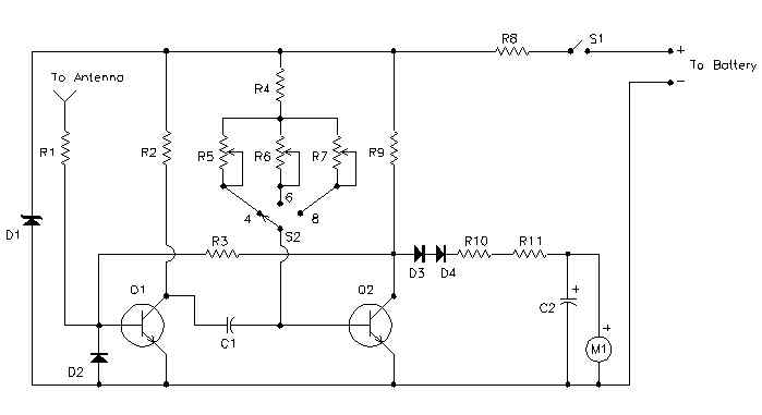
Wireless auto tachometer

INTRODUCTION
Anyone performing their own automobile tune-ups knows how important it is to know your engines speed. With this tachometer, you can measure your engines speed without any connections or annoying timing lights.

circuit diagram
This is the schematic of the Tach


Notes

  1. Calibrate the unit as folows:
    1. Set up this circuit:

      This is the setup for calibrating the Tach

    2. Turn on the Tach and allow a few minutes for temperature stabilization.
    3. Set S2 to 4 cylinders and adjust R5 for a meter indication of 180 (1800 rpm).
    4. Set S2 to 6 cylinders and adjust R6 for a meter indication of 120 (1200 rpm).
    5. Set S2 to 8 cylinders and adjust R7 for a meter indication of 90 (900 rpm).
  2. To use the Tach, turn it on and let it sit for one minute to allow for temperature stabilization. Extend the antenna, select the right number of cylinders and hold the unit over the engine. If the reading is erratic or the needle jumps around, move the antenna closer to the ignition coil or spark plug wires.
The unit draws power from the car battery. If it is connected backwards, it will not work, but it won't be damaged.

parts required

Part
Total Qty.
Description
Substitutions
C110.47uF Capacitor
C2147uF Electrolytic Capacitor
D118V 1W Zener Diode
D2, D3, D431N914 Diode
M11200uA Meter
Q1, Q222N3391A Transistor
R1, R2, R931K 1/2 W Resistor
R3147K 1/2 W Resistor
R4110K 1/2 W Resistor
R5, R6225K Trim Pot
R7110K Trim Pot
R81200 Ohm 2 W Resistor
R10115K 1/2 W Resistor
R1112.2K 1/2 W Resistor
S11SPST Togglae Switch
S21Three Position Single Pole Rotary Switch
MISC1Telescoping Radio Antenna, Enclosure, Power Cable and Battery Connector


August 13, 2009

SIMPLE ELECTRONIC DECISION MAKER

ELECTRONIC DECISION MAKER
A Simple circuit that makes decision for you within a FLASH....
press "S1" to switch on the circuit and then S2 to make a decision.

Circuit Diagram

Parts List
  • 1 - 390R
  • 2 - 1K2
  • 2 -33K
  • 2 -100K
  • 1 -1N4002 power diode
  • 2 - LED
  • 2 -0.1uF Capacitor
  • 2 - BC548 PNP
  • 1 - slide switch
  • 1 - push button

August 11, 2009

TRAFFIC LIGHTS

TRAFFIC LIGHTS

  • As well as the 4017 chip you will need a Hex (6) INVERTER and a Quad (4) AND gate chip.
  • Don't forget that all three chips need power connected to the correct pins.
  • The six diodes are Light Emitting Diodes (LED's).
  • The 470k and 4.7 uF control the speed at which the lights change

August 09, 2009

Transistor tester circuit

Transistor tester circuit

Description

Here is a very simple circuit that can b e used to check the hfe of transistors. Both PNP and NPN transistors can be checked using this circuit. Hfe as high as 1000 can be measured by using this circuit.The circuit is based on two constant current sources build around transistors Q1 and Q2.The Q1 is a PNP transistor and the constant current flows in the emitter lead. The value of constant current can be given by the equation; (V D1 -0.6)/ (R2+R4).The POT R4 can be adjusted to get a constant current of 10uA.

The Q2 is an NPN transistor and the constant current flows into the collector lead. The value of this constant current can be given by the equation; (VD2-0.6)/(R3+R5).The POT R5 can be adjusted to get a constant current of 10uA.This constant current provided by the Q1 circuit if the transistor under test is an NPN transistor and by Q2 circuit if the transistor under test is a PNP transistor is fed to the base of transistor under test. This current multiplied by the hfe flows in the collector of the transistor and it will be indicated by the meter. The meter can be directly calibrated to read the hfe of the transistor.

Circuit Diagram

August 03, 2009

Long duration timer circuit

Long duration timer circuit

Description

This timer circuit can be used to switch OFF a particular device after around 35 minutes. The circuit can be used to switch OFF devices like radio, TV, fan, pump etc after a preset time of 35 minutes. Such a circuit can surely save a lot of power.

The circuit is based on quad 2 input CMOS IC 4011 (U1).The resistor R1 and capacitor C1 produces the required long time delay. When push button switch S2 is pressed, capacitor C1 discharges and input of the four NAND gates are pulled to zero. The four shorted outputs of U1 go high and activate the transistor Q1 to drive the relay. The appliance connected via the relay is switched ON. When S2 is released the C1 starts charging and when the voltage at its positive pin becomes equal to ½ the supply voltage the outputs of U1 becomes zero and the transistor is switched OFF. This makes the relay deactivated and the appliance connected via the relay is turned OFF. The timer can be made to stop when required by pressing switch S1.

Circuit diagram

Construction

  • Assemble the circuit on a good quality PCB or common board.
  • The circuit can be powered from a 9V PP3 battery or 12V DC power supply.
  • The time delay can be varied by varying the values of C1&R1.
  • The push button switch S2 is for starting the timer and S1 for stopping the time.
  • The appliance can be connected via contacts N1 & N2 of the relay RL1.
  • The IC U1 is 2 input quad NAND gate 4011.

August 02, 2009

Load Sensing Power Switch

Introduction:-

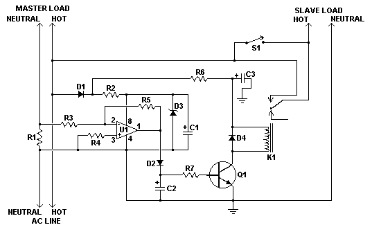
This circuit will automatically switch on several mains-powered "slave" loads when a "master" load is turned on. For example, it will switch on the amplifier and CD player in a stereo system when the receiver is turned on. It works by sensing the current draw of the "master" device through a low value high wattage resistor using a comparator. The output of that comparator then switches on the "slave" relay. The circuit can be built into a power bar, extension cord or power center to provide a convenient set of "smart" outlets that switch on when the master appliance is powered (turn on the computer monitor and the computer, printer and other peripherals come on as well).

Diagram:-

Schematic for Automatic Load Sensing Power Switch

click on the image for better quality................

Parts:-

Part
Total Qty.
Description
Substitutions
C1, C3210uF 35V Electrolytic Capacitor
C211uF 35V Electrolytic Capacitor
R110.1 Ohm 10W Resistor
R2127K 1/2W Resistor
R3, R411K 1/4W Resistor
R51470K 1/4W Resistor
R614.7K 1/2W Resistor
R7110K 1/4W Resistor
D1, D2, D431N4004 Rectifier Diode
D311N4744 15V 1 Watt Zener Diode
U11LM358N Dual Op Amp IC
Q112N3904 NPN Transistor
K11Relay, 12VDC Coil, 120VAC 10A Contacts
S11SPST Switch 120AVC, 10A
MISC1Board, Wire, Socket For U1, Case, Mains Plug, Socket


Notes:-

  1. This circuit is designed for 120V operation. For 240V operation, resistors R2 and R6 will need to be changed.
  2. A maximum of 5A can be used as the master unless the wattage of R1 is increased
  3. S1 provides a manual bypass switch.
  4. THis circuit is not isolated from the mains supply. Because of this, you must exercise extreme caution when working around the circuit if it is plugged in.

LASER Power Supply

Diagram:-

This is the schematic of the laser power supply
click on the image for better quality........................

Parts:-

Part
Total Qty.
Description
Substitutions
R1110 Ohm 10W Or Greater Resistor
R21Ballast Resistor, See "Notes"
D1, D2, D331N4007 Silicon Diode
C1, C2, C330.1 uF 2000V Capacitor
T119V 1A Transformer
S11115V 2A SPST Switch
MISC1Case, Wire, Binding Posts (for output), Line Cord

Notes

  1. T1 is an ordinary 9V 1A transformer connected backwards for step up.
  2. R1 MUST be installed on a LARGE heatsink. A good heatsink is the metal case the supply is built in.
  3. R2 Protects the laser tube from excess current. It should be soldered directly to the anode terminal on the tube. To find R2, start with a 500K 10W resistor and work down until the tube lights and remains stable.
  4. If you have trouble with the tube not starting easily, use a longer anode lead that is wrapped around the tube.
  5. Depending on the transformer you use, the circuit may or may not work. I cannot guarantee the operation of this circuit. Build at your own risk. Some transformers contain very few secondary windings which will quickly saturate the core and basically act like a direct short. The more secondary windings (that is, primary in this circuit) the better.

Sound Level Meter

introduction:-
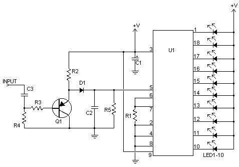
This nifty sound level meter is a perfect one chip replacement for the standard analog meters. It is completely solid state and will never wear out. The whole circuit is based on the LM3915 audio level IC and uses only a few external components. This circuit can also be integrated into audio amp projects.

Diagram:-

Schematic for sound level meter

click on the picture for better view..............

Parts:-

Part
Total Qty.
Description
Substitutions
C112.2uF 25V Electrolytic Capacitor
C2, C310.1uF Ceramic Disc Capacitor
R1, R321K 1/4W Resistor
R2110K 1/4W Resistor
R41100K 1/4W Resistor
R511M 1/4W Resistor
D111N914 Silicon Diode
Q112N3906 PNP Transistor
LED1-LED1010Standard LED or LED Array
U11LM3915 Audio Level IC
MISC1Board, Wire, Socket For U1


Notes:-

  1. V+ can be anywhere from 3V to 20V.
  2. The input is designed for standard audio line voltage (1V P-P) and has a maximum input voltage of 1.3V.
  3. Pin 9 can be disconnected from +V to make the circuit use a moving dot display instead of a bar graph display.

call recorder

Introduction:-
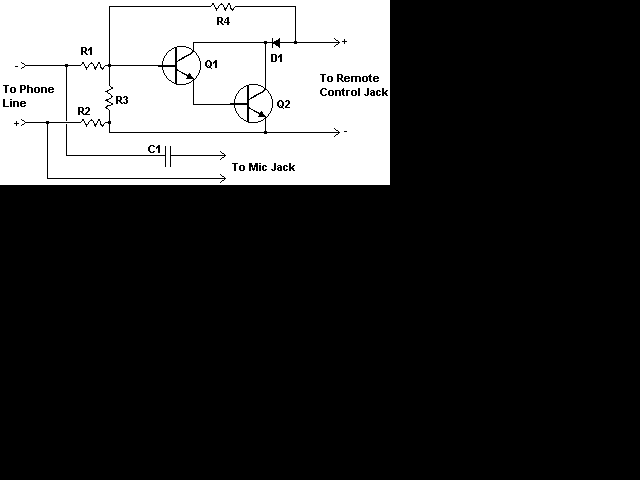
circuit lets you record your phone conversations automatically. The device connects to the phone line, your tape recorder's microphone input, and the recorder's remote control jack. It senses the voltage in the phone line and begins recording when the line drops to 5 volts or less.

Diagram:-

This is the schematic of the Telephone Recorder

click on the image for better quality..................

Parts:-

Part
Total Qty.
Description
Substitutions
R11270K 1/4 W Resistor
R211.5K 1/4 W Resistor
R3168K 1/4 W Resistor
R4133K 1/4 W Resistor
C110.22uF 150 Volt Capacitor
Q1, Q222N4954 NPN Transistor
D111N645 Diode
MISC1Wire, Plugs To Match Jacks On Recorder, Board, Phone Plug

Notes:-


  1. The circuit can be placed anywhere on the phone line, even inside a phone.
  2. Some countries or states require you to notify anyone you are talking to that the conversation is being recorded. Most recoders do this with a beep-beep. Also, you may have to get permission from the phone company before you connect anything to their lines.

Remote Telephone Ringer

Introduction:-
This remote telephone bell ringer allows you to use a large (and loud) external bell in place or in addition to the built in (and rather wussy) ringer in most modern telephones. This is ideal for large outdoor areas, noisy shops or those hard of hearing. Most any large bell can be used as the circuit can be easily adjusted for various supply voltages.

Diagram:-


click on the image for better quality......................

Parts:-

Part
Total Qty.
Description
Substitutions
C110.47 300V Capacitor
C2147uF 25V Electrolytic Capacitor
R111K 1/4W Resistor
R2110K 1/4W Resistor
R311K Pot
R412K 1/4W Resistor
Q116A, 200V TRIAC
Q216A, 200V SCR (106, Etc.)
D111N4774 Zener Diode
D2, D321N4007 Rectifier Diode
U114N33 Opto Isolator
BELL1Large Bell (Fire Bell, School Bell, Etc.)
MISC1Board, Wire, Socket For U1, Case

Notes

  1. Virtually any TRIAC and SCR will work for Q1 and Q2 as long as the voltage rating is high enough. Q2 needs enough current capacity to handle the full load of the bell.
  2. To adjust R3, call the phone line on which the ringer is installed and adjust the pot until the bell begins to sound consistently.
  3. Make sure to check with local authorities before you connect a homemade device to your phone lines. Some areas mandate that only approved devices can be connected to the loop. This circuit provides an opto-isolator to prevent cosstalk between the phone line and power supply as well as to avoid ground loops.

Aircraft Radio Communications Receiver

Introduction:-
The communications between commercial aircraft and the ground can be interesting, amusing and sometimes even disturbing. However radios that receive the approximately 220MHz to 400MHz band commonly used for aircraft (both military and commercial) are not easily found. And scanners can be complicated, large and expensive. With an easy to build circuit such as this one, everyone can enjoy listening in on these conversations.

Circuit diagram:-


click on the picture for better quality................

Parts:-

Part
Total Qty.
Description
Substitutions
R1, R3247K 1/4W Resistor
R2110K 1/4W Resistor
R414.7K 1/4W Resistor
R515K Linear Taper Pot
R612.2K 1/4W Resistor
C1, C2, C3, C640.001uF Ceramic Disc Capacitor
C412.2pF Ceramic Disc Capacitor
C511pF Ceramic Disc Capacitor
C7115uF 15V Electrolytic Capacitor
C8118pF Variable Capacitor
D111N82 Diode
Q112N918 NPN Transistor
L11See Notes
L211.8uH Inductor
ANT11Approx. 18 Inch Wire Antenna
MISC1PC Board, Wire, Knob For C8


Notes:-

  1. L1 is made by winding 2 turns of 22 AWG magnet wire on a 5/32 drill bit. This inductor can be modified to shift the frequency range of the circuit.
  2. The antenna can also be placed at the anode of D1 if overload is a problem with it connected to the emitter of Q1
  3. R5 adjusts regen and thus sensitivity.

Crystal Radio

Introduction:-
The circuit is very simple with only 5 parts, but performs very nicely when used with the right size antenna.

Diagram:-

This is the schematic of the Crystal Radio

click on the image for better view...................

Parts:-

Part
Total Qty.
Description
Substitutions
C11Tuning Capacitor (See Notes)
D111N34 Germanium Diode
L11Loopstick Antenna (See Notes)
SPKR11Crystal Earphone
MISC1Wire, Board, Wire For Antenna, Knob For C1


Notes:-

  1. C1 and L1 can be bought, or salvaged from an old AM radio (which is where I got mine). You may need to experiment with the connections on L1 in order to get the best (or any) signal.
  2. You may or may not need the ground connection. I never use it and the radio usually works fine without it.
  3. The bigger the antenna, the more stations you pick up and the louder you hear them. On my radio, I get about 10 stations, 3 of which are very loud in the earphone. Of course, not everyone has room for a 60' antenna...
  4. A 47K resistor in parallel with the earphone will help properly load the detector

Horn Beep Canceller

DEFINITION:-
It's a great convenience that most modern cars come with a built in alarm, however it is nothing but noise pollution that the horn sounds when the alarm is armed. Disconnecting the alarm system from the horn relay will eliminate this, but prevent the horn from sounding in the even of an actual alarm. This circuit serves to silence the arming beep yet maintain the alarm by introducing a small delay into the signal. It sits between the alarm and horn relay. The alarm must provide a constant horn signal for at least 3 seconds before the horn relay is activated. That way the quick "beep" will never activate the horn relay, while the constant alarm signal will.

Diagram:-


Components required:-

Part
Total Qty.
Description
Substitutions
C110.01uF Ceramic Disc Capacitor
C21100uF 35V Electrolytic Capacitor
R111K 1/4W Resistor
R2110K 1/4W Resistor
R3115K 1/4W Resistor
R41470 Ohm 1/4W Resistor
D1, D3, D431N4004 Rectifier Diode
D21Red LED
U11555 Timer IC
K11SPST 12V Automotive Relay
MISC1Board, Wire, Socket For U1, Case

DOOR BELL FOR DEAF CLICK HERE

Electronics is the study and use of electrical that operate by controlling the flow of electrons or other electrically charged particles in devices such as thermionic valves. and semiconductors. The pure study of such devices is considered as a branch of physics, while the design and construction electronic circuits to solve practical problems is called electronic engineering.

Popular article