Bread Board
A bread board is also known as a project board, It has got itself a place in every electronics hobbyist because of its "User Friendly" Nature, a bread board needs no soldering and already it is connected internally, lets see about it in detail.
This is how a bread board looks
A bread board is available in many shapes and sizes and has a facility to connect many boards as you like.
Connections in a Bread Board
NOTE: In some bread boards the top and bottom are not fully linked only 5 pins are linked.
Working
The heart of the solder-less breadboard is a small metal clip that looks like this: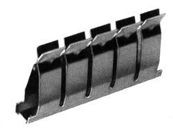
The clip is made of nickel silver material which is reasonably conductive, reasonably springy, and reasonably corrosion resistant. Because each of the pairs of fingers is independent we can insert the end of a wire between any pair without reducing the tension in any of the other fingers. Hence each pair can hold a wire with maximum tension.
Using a Bread Board
Example Connection
This shows how a 380 ohm resistor and an LED are setup on a breadboard. When a 9 volt battery is attached the LED lights. Try replacing the resistor with a higher value such as a 680 ohm resistor. The resistance will be greater and the LED should shine less bright.
Popular article
-
 Introduction:- The communications between commercial aircraft and the ground can be interesting, amusing and sometimes even disturbing. Howe...
 -
 EPE December 2008 Size : 12.6 MB Click the download button to start Password : electronicseveryday
 -
 APPLIANCE TIMER-CUM-CLAP SWITCH When planning for a weekend outing to return late in the evening, we are often in an ambivalence whether to ...
 -
Laws of Resistance 1. The resistance of a conductor varies directly as its length. 2. ...


0 comments:
Post a Comment