Touch Switch
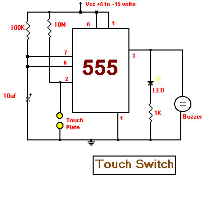
This circuit uses a 555 timer as the bases of the touch switch. When the plate is touched the 555 timer is triggered and the output on pin 3 goes high turning on the LED and the buzzer for a certain period of time. The time that the LED and the buzzer is on is based on the values of the capacitor and resistor connected to pin 6 & 7. The 10M resistor on pin 2 causes the the circuit to be very sensitive to the touch.
Circuit Diagram
July 26, 2009
Touch Switch
Electronics is the study and use of electrical that operate by controlling the flow of electrons or other electrically charged particles in devices such as thermionic valves. and semiconductors. The pure study of such devices is considered as a branch of physics, while the design and construction electronic circuits to solve practical problems is called electronic engineering.
Popular article
-
Starting Electronics Construction Techniques As a step-by-step guide from circuit design to finished product, this practical electronics boo...
-
In real who the transistor looks like.. its a semiconducting device commonly used to amplify (or) switch electronic signals The ...
-
Electronics For You March 2009 Size : 49.6 MB Click the download button to start Password : electronicseveryday
-
In real this is how an TRANSFORMER looks like.. the transformer is a device that transfers electrical energy from one end of the coil to th...


0 comments:
Post a Comment